Samuel Crawford
Undergraduate Degree: Electrical Engineering, M.I.T.
Masters Degree Candidate, University of Illinois Urbana-Champaign
Department of Electrical and Computer Engineering
Advisor:
Laird Thompson
Thesis Title: Wave Front Sensor Systems for Laser Guided Adaptive
Optics
Sam Crawford successfully completed both the optical and mechanical designs for the
UnISIS laser
guide star wave front sensor. The design of a wave front sensor requires optically
matching a miniature lenslet array to the CCD detector used to measure the wave front
irregularities. The lenslet array, specified for UnISIS by Mr. Crawford, is a custom-
designed 13x13 binary optic. Each lenslet is 400 microns square, so the entire array is
5.2 mm square. A highly magnified image of the lenslet array is shown below.
Sam Crawford's optical design work involved two optimizations: one for a single-
Pockel's-Cell system and a second for a double-Pockel's-Cell system. Both designs were
implemented in UnISIS: first the single system (used for the first time in 1999) and then
the double system (used in 2000 and thereafter). Matching the lenslet array to the high-
speed CCD sensor is not a simple exercise. The laser guide star is focused in the
intermediate field at 18 km altitude, and the optical design requires converting the return
light into a highly collimated beam, collimated to better than 1: 100,000. Only when the
Pockel's Cell optical switch sits in such a highly collimated beam can the Pockel's Cell
successfully hide or shield the CCD sensor from the bright flash of light associated with
low altitude Rayleigh scattering in the immediate vicinity of the telescope as the laser
fires.
Mr. Crawford is now working at the Jet Propulsion
Laboratory in Pasadena, CA.
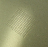 Shown here is the 13x13 lenslet array used to detect the UnISIS laser guide star return
signal. The lenslet was made by an epoxy replication process from a computer-generated
mold produced by photo-etching. As stated above, the entire array is 5.2 mm on a side
with 400x400 micron lenslets. The epoxy is deposited on a 1 inch diameter substrate that
extends far beyond the borders of this image. Each lenslet is square and closely packed
adjacent to its neighbors, so greater than 95% of the light incident on the array is passed
on to the CCD detector. Because the laser guide star is generated at 351nm, the lenslet is
anti-reflection coated for this wavelength.
Shown here is the 13x13 lenslet array used to detect the UnISIS laser guide star return
signal. The lenslet was made by an epoxy replication process from a computer-generated
mold produced by photo-etching. As stated above, the entire array is 5.2 mm on a side
with 400x400 micron lenslets. The epoxy is deposited on a 1 inch diameter substrate that
extends far beyond the borders of this image. Each lenslet is square and closely packed
adjacent to its neighbors, so greater than 95% of the light incident on the array is passed
on to the CCD detector. Because the laser guide star is generated at 351nm, the lenslet is
anti-reflection coated for this wavelength.