One of the major challenges of the UnISIS design was to define a scheme for sharing the 2.5-m telescope optical system between the out going laser beam and the incoming science beam. The challenge had two parts. The first was the mechanical issue of getting a precision alignment between the UnISIS subsystems and the telescope optical axis. The second was an issue of timing. The laser is pulsed so the telescope optical axis must be momentarily blocked while the laser fires. This first section describes the mechanical alignment issues. The second section below describes how the telescope optical axis is momentarily blocked with reflective spots on a 10,000 RMP rotating disk.
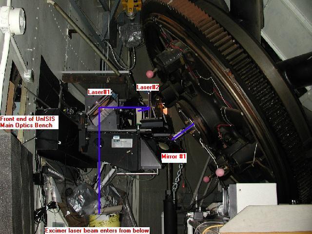
The 2.5-m Telescope at Mt. Wilson floats on two mercury bearings, one in the north pier and the other in the south pier. During the traditional operation of the Coude spectrograph, the telescope pupil was often seen to drift as the telescope moved across the sky. To make effective use of the 2.5-m telescope with UnISIS, the pupil drift had to be either (1) eliminated or (2) corrected in real time as the telescope moves across the sky. Anticipating that the second option would be necessary, the link between the telescope optics and the UnISIS Main Optics Bench consists of two remote-controlled tip-tilt mirrors. Only the first of these is visible in the picture below (labeled Mirror # 1). The second mirror, which is hidden behind other components, intercepts the telescope optical axis and directs it onto the UnISIS Main Optics Bench.
With the link between the Main Optics Bench and the 2.5-m Telescope under control, the remaining alignment issue is to force the Excimer laser beam onto the common optical axis. The Excimer laser beam is shown schematically as a blue line in the drawing below. This final challenge is met with a precision alignment of the two mirrors designated Laser #1 and Laser #2. (Those who look carefully at this image will see an obstruction in the laser beam path immediately after the mirror Laser #2. This is an alignment target that is lowered when the laser is firing.)
A huge gear dominates the upper portion of the picture. This is the telescope's
right ascension drive gear. The telescope's
Coude optical axis (the telescope's south polar axis) sits in the center of the
gear where a blue line has been added to show the path of both the out-going laser
beam and the in-coming science light.
On the left hand side of the picture is the front end of the UnISIS Main Optical
Bench (the large black rectangle protruding from the left wall). Sitting in the
center if the picture is the complex optical system where the beam-combining takes
place.
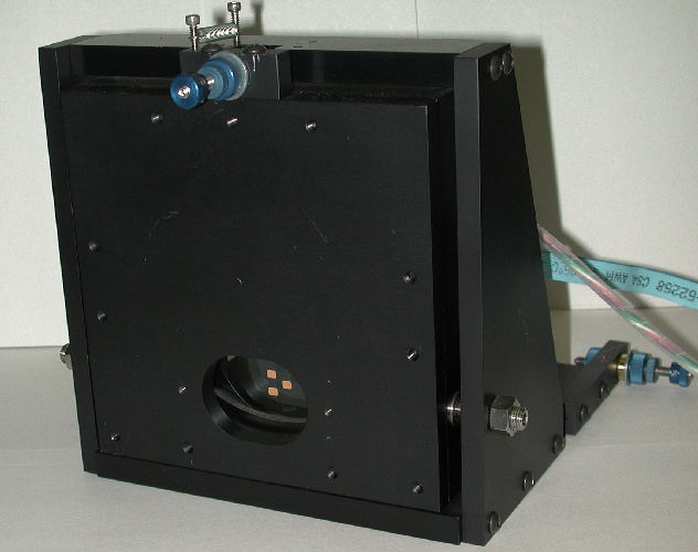
Three small reflective spots can be seen through a port in the front mount-plate
of the rotating disk. These spots are close to the outer radius of a glass disk
that is hidden behind the front mount-plate. The disk sits at a carefully
selected point along the telescope optical axis and spins at 10,000 RPM. Starlight
shines through the disk at all times and continues onto the UnISIS Main Optics Bench
for adaptive optics correction.
As the small spots flash through the optical axis, the starlight is momentarily
interrupted. The Excimer laser that creates the laser guide star is run in
perfect synch with this rotating disk. In fact, the signal to fire the laser
comes from an encoder attached to the disk's motor-drive. When a reflective
spot is perfectly positioned on axis, the laser fires, and the powerful beam
of laser light hits the reflective spot and is
projected up the telescope optical axis and into the sky. Any laser light that
happens to be scattered back in the direction of the telescope will hit the primary
mirror approximately 120 micro seconds after it is emitted by the laser. The disk
must spin at high speed because the reflective spot has to move out of the way
by the time the laser guide star returns from 18 km altitude so it can pass
through a clear part of the rotating disk and onto the UnISIS Main Optics Bench
where a very fast electro-optic shutter isolates the scattered light from the
altitude range 17.75 km to 18.25 km. This return signal looks virtually identical
to a natural star and the UnISIS computer system analyzes this light to determine
how the deformable mirror has to be distorted to remove the aberrations that the
atmosphere has put into the wavefront. The following cycle -- fire the laser -
wait for it to return - capture the
return signal - analyze the atmospheric distortion - adjust the deformable mirror --
is executed in less than 770 millionths of a second.