The UnISIS reconstructor computer was originally based on an early Pentium PC (ca. 1996) and a PCI bus extender chassis that held custom-built interface cards designed to communicate with two wavefront sensors as well as two quad-C30 DSP boards. The DSP boards received the camera data and handled the matrix multiply for the AO correction. The LGS wavefront camera data entered the bus extender on a fiber optic line, and the NGS wavefront camera data entered the bus extender on several large parallel lines. The performance of this old system was limited to 167 Hz for LGS AO work and 246 Hz for NGS work.
In October, 2004, the old reconstructor computer system was replaced with a Real-Time Linux system running on a 2.4 GHz Pentium platform. The calculation speed of the Pentium is fast enough to eliminate the need for the DSP system. The LGS camera remains the same as in the original system (CCD39 sensor 80x80), but the speed of its Leach electronics was upgraded by installing a new timing board which also provides faster fiber optics data transfer. The original NGS wavefront camera (an MIT 64x64 sensor running on electronics built by Jim Beletic) was retired, and it was replaced with a CCD39 sensor (80x80) that also runs with fast Leach camera electronics. Both camera data streams enter the Real-Time Linux system on the PCI bus. After the matrix calculation is complete, output instructions for the deformable mirror (DM) appear on the PC parallel port. These signals are downloaded into the DM control electronics during a period that lasts approximately 87 microseconds.
As described in the UnISIS Performance section, the new Real-Time Linux LGS system can download a wavefront image, complete the matrix multiply, and output the DM commands at a frame rate of 1.48 KHz even though the LGS system sync is set by the Excimer laser repetition rate. The new Real-Time Linux NGS system can download a wavefront image, complete the matrix multiply, and output the DM commands at a frame rate of 1.28 KHz if the exposure time on the NGS camera is set to zero. Of course, in real operation we might set the exposure time to 0.5 ms in which case the UnISIS LGS side will work at 780 Hz while if we set the exposure time to 1 ms the LGS system will work at 560 Hz. Why is the LGS system so much faster than the NGS side? Because the LGS exposure is extremely short at 20 microsec.
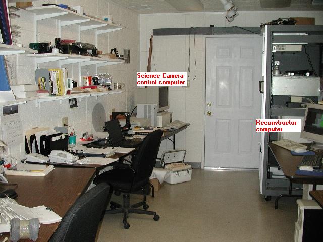
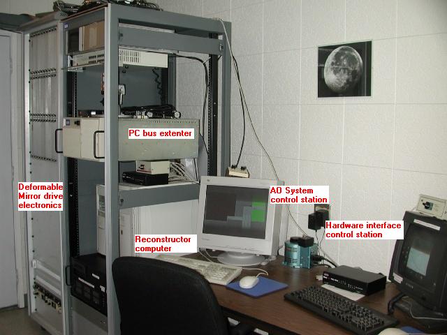
The two pictures show here were taken in the UnISIS Control Room prior to October 2004. They
will soon be updated to show the new system.
The remainder of the UnISIS Control Room provides office space for those
who work with the system and limited space for equipment development and testing.